Categories
Commissioning Construction Facilities and terminals Rapidways Safety Stations Technical

safety in waiting

Bus rapid transit (BRT) systems like viva use a variety of design features to make travel faster, but the primary feature is dedicated transit lanes that allow buses to bypass regular traffic. BRT systems around the world take different approaches as to where those lanes go. Some use separate lanes beside the roadway. Here in York Region, the vivaNext system uses median rapidways that run down the centre of the road.

median benefits

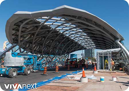
A major benefit of median rapidways is how they minimize conflicts with driveways and business access. However, this design requires passengers to wait for their buses in the middle of high-volume thoroughfares – such as Highway 7 West at the new Vaughan Metropolitan Centre rapidway station. Utmost consideration was given to design strategies that ensure the safety of passengers while they wait for their buses.

crash-load strength

The VMC Station’s most crucial safety protection are the white concrete barrier walls which run the length of the station on both sides, separating the waiting area from traffic lanes. With the wall’s white architectural concrete finish, curves that echo those on the station roof and tapering design that flows into the planters and ramps near the crosswalk, this wall is a key aesthetic feature of the new station. But don’t be fooled by its good looks: this wall is a brute.

It’s designed to withstand crash loads, the potential forces involved in a traffic collision. Crash-proof walls have to meet strict criteria on factors such as design, materials and construction. These specifications are set by Ontario Provincial Standards, and before we received approval to begin construction, every element of the design was scrutinized to ensure it met or exceeded those requirements.

standard scrutiny

Design standards dictate things like the height and thickness of the wall, how much rebar – steel reinforcements – is incorporated, how much it will weigh, and how the wall will be fixed to the base. Standards apply to the type of materials used for the concrete wall, the aggregate used to mix the concrete, the steel used in the rebar, even the coatings on the steel. Likewise, standards dictate the construction itself, ranging from how the concrete is cured to how edges are finished.

Although safety comes first, we made sure it looks good, too.

So now you know all the thought that went into protecting you while you wait for your YRT/Viva bus, we hope you admire the design of the station, relax, and enjoy this impressive new addition to the Vaughan Metropolitan Centre.

Categories
Commissioning Construction Facilities and terminals General Rapidways Stations Technical

a modern take on the ancient dome

Here’s a question: what do some of the most impressive structures in the world, including many of the great cathedrals of Europe and the Pantheon in Rome, have in common with our new bus rapid transit station at the Vaughan Metropolitan Centre?

The answer: they’ve all followed the same basic construction technique for building a dome, which has been around for at least 2,000 years.

Domes have traditionally been reserved for a select number of important buildings which need to be impressively open and dramatic. Another reason there aren’t a lot of domes is because they’re more difficult to build compared to standard rectangular buildings. We loved the idea of creating an open and airy space for the Vaughan Metropolitan Centre rapidway station, making it big enough for viva buses to drive right through. We also wanted it to be special, and symbolic of Vaughan’s new downtown.

Although building materials may have evolved over the past 2,000 years, the general approach for building domes hasn’t really changed. First, strong, deep foundations are constructed to take on the full weight of the dome. Then, a temporary support structure is built. Gradually the permanent exterior shape is created up around the support structure until the dome is closed at the top. Once the dome is complete and able to support itself, the temporary support structure is removed, piece by piece.

Ancient domes would have had wooden temporary support structures, with the outer dome made of stones added one at a time. Although the materials we used are modern, we followed the same classical construction technique. First we built a steel temporary structure. Over that we installed the station’s outer dome, a steel frame welded together one segment at a time.

With the outer steel structure fully installed and all the structural welding complete, we carefully removed the temporary support structure one piece at a time, which took a couple of weeks. After this process was complete, construction inside the station began.

All the weight of the station is supported by the subway structure underneath the station, and 25 metre-deep piles or caissons which extend underground to the same level as the subway.

With its glass and steel shell exterior and high-tech comfort and amenities inside, we know you’re going to love using our new station for its modern look and functionality. But you can be proud of the fact that, from an architectural standpoint, it’s joining a pretty special group of buildings that have been built to stand the test of time.

Categories
Commissioning Construction Going Green Innovation Safety Stations Technical Urban Planning

rain, rain, go away

Our new rapidway station at Vaughan Metropolitan Centre is ready for the rain, innately designed to handle a downpour and keep those pesky puddles off the road.

Large structures like the new bus rapid transit station shed a lot of rain during storms. With the size of the station’s roof, the volume of water collecting from even light rain storms would be enough to create some pretty major puddles.

Water management has been a key design consideration for the station since day 1. Letting runoff drain freely onto the roads isn’t an option since the station is right in the middle of Highway 7. Here’s the rundown on how we’re managing runoff.

Water management strategy includes features built into the station’s design, and the design of the road and storm water management systems around the station.

Gutters run along the curved station roof between the skylight and the roof panels, designed to collect and funnel water to the ends of the station. At that point, brow gutters – shaped like eye-brows – will drain the water into downspouts on the sides of the station, which then drain safely into underground catchbasins connected to the storm water management system.

But that’s not all! Water from the middle portion of the roof, below the roof gutters, will drain off the roof onto the road. Generally at our vivastations, the road design ensures water doesn’t become puddles.  A very gradual slope away from the station to the curb lane directs the water into a series of curbside storm sewers and catch basins.

However, the VMC station is so much larger than the other stations, there’s simply too much water to direct across the road. Instead, we drain the water closer to the station.

We’ve built up the road surface so that its highest point is 1.2 metres away from the station.  Water draining off the station will be naturally directed back towards the station, running along the curb into a series of catchbasins and into the storm sewers.

We know that rain gutters and catchbasins aren’t the most glamourous features of the new station, but on a rainy day, we’ll all be glad they’re there.

Categories
Bridge Expansion Construction Rapidways Technical Uncategorized

bridge expansion >> driving piles and pouring piers

When you go under a bridge, what do you see? Huge concrete columns – piers – that support it. The five-metre expansion of the bridge on Highway 7 West over Highway 400 is becoming fully visible as the new piers are completed. In the photo above you can see the three completed piers and crews pouring the concrete cap for the fourth.

Each one of these piers is held up with a set of nine piles. Piles are long poles driven straight down, until they reach a surface solid enough to hold everything above. In this case, the piles are each nine metres long.

In the photo, the tall piece of equipment beside the west abutment wall is the pile driver, which is – as you’d expect – used to drive the piles into the ground.

On top of the pile-supported-piers, there will be bridge footings, girders, and a wider deck to make room for cars and trucks – as well as buses on new vivaNext dedicated rapidway lanes and a multi-use path for pedestrians and cyclists.

While it’s true that piers are just a part of the bridge, the bridge is part of a road, which is part of a rapid transit system, which connects people to where they need to go.

Next time you go under a bridge, look at the piers that support it, and the engineering and construction that went into them.

We’re building rapid transit, and along the way making infrastructure – built to last.


For information on ongoing vivaNext projects, be sure to subscribe to email updates, and follow us on Twitter. Questions or comments? Comment below or email us at contactus@vivanext.com.


Categories
Construction Rapidways Technical Uncategorized

what’s gravity & slope got to do with it?

While we’re building the rapidway projects, it’s not unusual for us to be talking a lot about retaining walls. If you’ve ever wondered why so much of our work seems to involve retaining walls, the answer can be summed up in two words: gravity and slope.

Simply put, retaining walls prevent soil from sliding down a slope. If a slope is very gradual as you might see on a lawn or wide flowerbed, for the most part the soil and earth pretty much stays put. But where there is a slope over a short distance that creates even a difference in grade, the force of gravity will make the soil slide downwards.

stopping soil slippage

The steeper the slope, the more likely it is that the soil will slide. If you have a lawn that’s even a few centimetres higher than an adjacent driveway or sidewalk, you’ll know that without some kind of edging, eventually the dirt will flow down onto the pavement.

Retaining walls are like edging; they’re structures that keep the soil in place where grades need to change within a short distance. And retaining walls can be short or high. For example, a curb is essentially a very short retaining wall.

where retaining walls fit in on the rapidway

In many stretches along our rapidway construction zones, the adjacent land is either higher or lower than the roadway – in some cases the difference is only a few centimetres, in others it’s a metre or more.

Because we’re widening the road, that difference in grade level now has to be made up over a shorter horizontal distance, making the slope steeper than it was before. In areas where the resulting grade difference between the road and the land slope is very steep, a retaining wall is needed to keep the soil in place.

where design is king

Some of our retaining walls are essentially high curbs; others are high structures requiring handrails and complex foundations.

Every one of our rapidway segments has a significant number of retaining walls, each requiring its own design, approvals and construction process. In all cases, retaining wall construction takes place once utilities have been moved out of the way, and needs to be finished before road widening can be started.

With so many retaining walls forming part of the new streetscape, design considerations are of major importance. A lot of effort goes into ensuring that the new retaining walls contribute to the aesthetics of the streetscape as well as be functional.

Different materials and finishes are used for different walls, from pre-formed wall blocks similar to what you’d use in your own garden, to poured concrete with decorative exterior designs.  Design approaches vary depending on how high the wall is, what kind of foundation it requires, and what it is adjacent to. And if the wall or adjacent slope is especially steep and the wall is next to a sidewalk, it will also get a specially designed handrail.

So the next time you see a bulletin advising about retaining wall work, think of gravity and slopes, and you’ll know that’s why we’re building these additional structures.

For information on ongoing vivaNext projects, be sure to subscribe to email updates, and follow us on Twitter. Questions or comments? Comment below or email us at contactus@vivanext.com.

Categories
Communications Construction Rapidways Technical Urban Planning

the unique challenge of working around business, residential and other private property

When you’re talking about private property, chances are you’re picturing someone’s home or business, or maybe a piece of land with a fence around it. But did you realize that every square inch of York Region, as in every other jurisdiction in Canada, is actually owned by someone?

Typically, for projects like vivaNext, when work will be taking place on or near private property, we work with a range of property owners, whether it’s a private individual’s home or business or a different level of government. Here’s how it works:

During the earliest design phases, we map out the proposed design for the future roadway or facility, working with existing information about property ownership. For the most part, rapidways and facilities are intentionally designed to fit within property that is already owned by the future operators of our projects – for example, the Region of York or one of our local municipalities.

As the design process gets more detailed, we analyze how the proposed alignment will fit with the properties along the roadway. We also identify any impacts the project will have on each.

In some cases, such as where the road is being widened, the recommended design may show that we might need to encroach onto private property. Sometimes we may only need access onto private property during construction, and sometimes it’s permanent.

With the final design established, and depending on the nature and duration of the property impact for each property, we then follow a series of established procedures to come to an agreement with the owner.

The agreement will include clarification of how our work will affect their property, how long we’ll need access if it’s only temporary, and compensation if we’re acquiring some part of their property.

The options and arrangements will vary depending on the kind of property and what impact our project will have on it; for example, installing a rapidway across a bridge over a 400-series provincial highway will involve different issues and potential strategies with the property’s owner or representative. In this case, it’s the Ministry of Transportation on behalf of the Province of Ontario.

In all cases though, the process of working with property owners to work out access is a complex part of the design and pre-construction work, and involves many different team members including York Region Property Services, Legal Services, York Region Transit, our design builders as well as our project team.

But no matter who the owner is, being respectful of the rights of all our property-owning neighbours is a top priority for our project with dedicated staff like the Community Liaisons to help answer questions in the field.


Categories
Accessibility Safety Technical Urban Planning

making corners work for everyone

making corners work for everyone

In civil engineering-speak, curb radius refers to the curve of the curb as it goes around a corner; sometimes it’s a wide gentle bend, and sometimes it’s a tight right angle. So here’s a question: when’s the last time you waited at an intersection for the light to change and actually even noticed the curb radius?  If you’re like pretty much everyone else, probably never.

And yet, believe it or not, the curb radius is one of the most important components of streetscaping, and has a profound influence on how drivers and pedestrians use a street.

As you already know, streetscaping refers to all the elements making up the public spaces along our streets. Because a key vivaNext goal is to make everyone feel welcome on our streets, whether they’re walking, biking, waiting to hop on Viva, or driving, we pay a lot of attention to streetscaping considerations. This includes the curb radii for every single intersection and entrance along our rapidways.

The curb radius describes the shape of a corner, such as when two perpendicular streets come together at an intersection, for example. The curb radius is expressed as a number, taken from the radius of the curve connecting the curbs of the two streets. On a wide suburban corner, the curb radius might be as high as 35, whereas on an urban street corner, it might only be 2.

Most urban settings, including along our vivaNext rapidways, aim for a smaller curb radius wherever possible.  That’s because the smaller the curb radius, the shorter the distance a pedestrian has to walk to get to the other side of the road. A smaller curb radius has other impacts too. It results in more space at the corner, including more space for accessible ramps. It makes it easier to line up crosswalks with connecting sidewalks.  It improves the sightlines for pedestrians and makes pedestrians more visible to drivers. And it slows down turning movements for vehicles going around corners, which is safer for pedestrians.

Of course, curb radius design also considers the needs of drivers, including traffic volume, vehicle size, and their desired speed going around corners. It also has to take into account bike lanes, on-street parking, bus stops, emergency vehicles, and other design requirements.  Whether or not the road is part of a truck route may affect the curb radius, because trucks need a larger turning radius to be able to navigate turns while staying within their lane.

Our final curb radius design isn’t up to us alone, of course.  Our designs reflect standards and requirements set by York Region and the municipalities as part of their broader planning for their regional and local road networks. Those requirements in turn reflect the design standards from a variety of authorities including guidelines from the Transportation Association of Canada and the Ontario Ministry of Transportation.

There’s a lot involved in the design of a simple concrete curb than you probably would have guessed. But the final result is for a more welcoming, safe and accessible streetscape for all users.


Categories
Accessibility Construction Stations Subways Technical

matching the heights

matching the heights

With the extraordinary maneuvering required to install the roof sections of the VMC BRT station in its location in the centre of Highway 7, you might think the most challenging part of this project has been its incredible glass and steel canopy.

It’s true that installing the canopy of the station required a lot of planning and meticulous engineering. But actually, the coordination of the underground subway station with the BRT station above has been – and still is – a much more complex logistical challenge.

the mechanics of it all

Building the actual physical connections between the two structures was involved but not unduly complicated, similar to any building that has a framed structure on top of a concrete slab. Because the top of the station is wider than the lower part and overhangs at the edges, we couldn’t use rebar dowels, which are the most common construction method. Instead, we used mechanical couplings that enabled us to essentially bolt the top to the bottom.

working together

What makes the project more challenging is that the subway station is being built by the TTC, while the above ground BRT station is being built by vivaNext. With two different owners, and two different contractors, the project demands an intensive degree of coordination and planning.

Joint planning work began long ago, starting with establishing the specific requirements for how the project needed to be built, both below and above ground, and inside and outside the subway station. With the TTC building the subway station up to the surface, and vivaNext building the BRT station from the ground up, the heights of floors and ceilings had to line up perfectly.

top to bottom, inside and out

The vertical elements between the lower and upper floors – including the stairs, escalators and elevators – had to be installed early, with no margin for error. Escalators are very rigid, designed to fit perfectly between floors. And because the rapidway runs right through the station, the top of the escalator, stairs and elevator also had to align precisely with the existing level of Highway 7 outside.

At the same time as the TTC was building the lower levels of the subway station, we were outside building the civil works – the roadway, curbs and gutters – that surround the BRT station. Again, because the rapidway runs through the station, the heights of the underground parts of these elements had to fit with the height of the subway box below.

The BRT station is well on its way and is already a head-turner. In the not-too-distant future, all of this engineering and coordination will make it possible for you to step off the escalator at VMC subway station and easily make your way to the BRT station on Highway 7 and beyond.

See an artist’s rendering of the VMC BRT station once complete.


Categories
Construction Rapidways Stations Technical

making sparks fly

making sparks fly

If you’ve been near the future Vaughan Metropolitan Centre [VMC] vivastation recently, you’ve likely seen our welding crews up on man-lifts. And if you’re like most people, you probably didn’t give the welding process much thought – welding is welding, right? Lots of protective clothing, impressive clouds of sparks, and something gets permanently stuck to something else.

Of course, as always with all our engineering and construction activities, there’s so much more going on than meets the eye, and welding on the VMC station is no exception. Here’s the primer on what they’re doing up there, and what some of the complexities are.

Since we’re talking vivaNext, form and function both matter. There are two ways to join two pieces of metal: bolting them together, or welding them. Bolting works well enough, and is the most common method used on bridges, high rises and many other structures. But bolts show, and when the design – as for the VMC station – is for a smooth, seamless architectural look, bolts would be out of place. So welding was chosen as the method to join the pieces of steel throughout the structure.

Welding design takes into account the ultimate strength and performance needed from the structure being joined together, including the loads it will bear, and any flexibility it will require. In the case of the station’s steel superstructure, we are using “full penetration” welding. That means that the two elements being welded together are literally being fused into one piece. Rather than one piece being stuck onto the other, enough heat is applied that the two pieces melt and become one at a molecular level. With this type of welding, it’s not just one surface being glued to another; the joint literally goes through the full depth of the elements being connected. The resulting element is as strong structurally as one solid piece of material.

Once the weld is done, it is reviewed by the welding contractor for certification that the weld meets the required standards including having no impurities or voids. The reviews are generally done visually, although in some cases x-rays will be used. Our general contractor will also do their own quality control, and carry out random spot-checks on many of the welds.

In general, welding can be done until the temperature drops to -18 Celsius. But this specialized kind of welding requires warmer outside temperatures. When temperatures are -5 or below, some weld areas may need to be pre-heated with electrodes.

We’re moving as fast as we can to get the roughly 200 structural welds done, with welders working in shifts, each safely attached by full harnesses to a man-lift while they’re up high. Once the sparks are finished, and because it’s too cold out to paint steel, our last step will be to protect the welded areas with an anti-rust finish.

If you’re in the VMC area, we hope you’ll slow down and look around you. If you do, you’ll be able to admire up close its sleek, architectural lines, and understand all the work that went into making the steel superstructure smooth, strong and beautiful.


Categories
Construction Rapidways Studies Technical

designing for the future

Who can remember? Not so long ago Highway 7 in Markham and Richmond Hill was a suburban highway: a few isolated developments, lots of parking lots and open fields, but no sidewalks, no plantings, no bike lanes–and certainly no dedicated rapid transit bus lanes. Just look at it now!

In only a few years from start to finish, construction begins and is completed on each of the rapidway projects. In the world of infrastructure renewal, vivaNext construction projects are known to be implemented very efficiently, and we’re doing everything we can to maintain that great reputation.

years of work are behind the design

What’s not so apparent to the public is the lengthy design process that happens long before construction starts. Design of the many engineering and architectural elements must take place stage by stage. Throughout, the designers need to balance staying true to the original vision with making it work in different conditions and geographical areas.

a variety of disciplines at work

VivaNext uses a multi-disciplined design team including: engineers who specialize in civil, traffic, structural, geotechnical, electrical and transit systems; architects; environmental consultants; landscape architects, security experts and more.

many stakeholders weigh in

At each stage, different options and features are reviewed, adjusted and improved with input from municipal staff, utility companies, local conservation authorities, property owners and others. Depending on the location of the project, specific design issues are addressed in conjunction with the owners of adjacent infrastructure including GO Transit, 407 ETR, CN, and the Ontario Ministry of Transportation.

the stages of each project

The process is not a fast one; the Environmental Assessment process, which established the conceptual design for vivaNext, was begun in 2002, and the whole process for any one segment from Preliminary Engineering to service start may take 6 or more years. Here’s an overview of the stages each of our projects go through, before shovels can hit the ground.

•    Environmental Assessment [EA]: The EA examines alternatives and identifies a preferred design. The vivaNext conceptual design shows the approach for individual segments like the number of rapidway and traffic lanes, boulevards and planting zones and the arrangement of stops and stations. The EA then identifies potential design impacts on the natural and built environment, traffic, noise, drainage, property, etc., and proposed strategies to avoid or mitigate and monitor them.

•    Preliminary Design: This stage takes design to approximately 30% completion and establishes the outlines of the project including its alignment and profile, what additional property is needed to build the project, development of major components like bridges or culverts for water crossings, entrances and intersections, utilities, and listing permits and approvals.

•    Detail Design: This stage fleshes out the preliminary design for all elements. For example, preliminary design may identify that a high retaining wall will be needed at a specific location; 60% design will show the kind of foundation needed and the wall’s general construction; 90% design will show the colour and design of the material to be used on the outside of the wall, and 100% will show all details and specifications required to construct the work.

•    Issued-for-Construction Drawings: These are the final design drawings to be used by the contractors, once all approvals are complete.

By the time vivaNext is complete, all our projects will share the original design vision, but their individual design will reflect local requirements and various conditions. Each segment is tailor-made to be functional, convenient and beautiful, with the primary goal of providing a rapid transit system for the future. Which is, and always has been, the ultimate vivaNext design objective.